Determination of the concentration of solutions using a Rayleigh interferometer. Interferometers and their applications Rayleigh interferometer
Rayleigh interferometer
Animation
Description
The Rayleigh interferometer is one of the most sensitive interference devices to the difference in phase incursions of waves, which allows it to be used to accurately determine the refractive indices of gases at a pressure close to atmospheric (at this pressure, the corresponding refractive index differs from unity in the fourth to fifth decimal place) .
A schematic representation of the design of the Rayleigh interferometer is shown in fig. one.
Schematic representation of the design of the Rayleigh interferometer

Rice. one
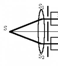
A beam of light from an almost point source S, which is at the focus of the lens, is converted by this lens into a parallel beam. Further, behind the lens, there is a diaphragm with two holes symmetrical about the main axis of the system - secondary sources S 1 and S 2, forming two parallel thin beams. These beams are then focused by a second lens onto a screen located in its focal plane. The result is an interference pattern of horizontal stripes, as shown in the figure. In this case, in the absence of additional objects with refractive indices n 1 (a cell with the gas under study) and n 2 (a phase shift compensator with a known controlled phase shift of the optical radiation in it), the zero maximum of the interference pattern lies on the system axis. The zero maximum is the maximum corresponding to the zero path difference D of the waves forming the interference pattern. When using broadband radiation (for example, natural light), it is easily distinguished from the higher-order maxima m:
D \u003d m l 0,
where l 0 is the central wavelength of the radiation spectrum.
Indeed, it is easy to understand that it is the only one that has the initial white color, while the higher-order maxima are “stretched into the spectrum” due to the fact that the maximum conditions are achieved at different displacements from the center of the pattern for different wavelengths of the beam spectrum.
If we now introduce into two beams propagating in the interlens space (the so-called interferometer arms) a cell of length L with the gas under study n 1 and a controlled optical delay n 2 (for example, the same cell with a gas whose refractive index depends on pressure is known) , then the beams will receive an additional path difference:
D 1 \u003d L (n 2 -n 1 ).
Thus, the zero fringe of the interference pattern will shift, and the center of the field will acquire color.
To “return the picture to its place”, it is necessary to equalize the refractive indices of the studied gas and the reference gas in two cuvettes, which is achieved by varying the pressure of the latter. As a result, having restored the centrality of the zero “white” band (and this can be done with high accuracy, on the order of 1/40 of the band, D m Ј 1/40 ), we obtain accurate information about the refractive index of the gas under study. Real instruments, made according to the scheme of the Rayleigh interferometer, make it possible to measure the differences in the refractive index from unity according to the formula:
(n-1)= l 0 D m/L » 10 -8 .
Timing
Initiation time (log to -8 to -7);
Lifetime (log tc -7 to 15);
Degradation time (log td -8 to -7);
Optimal development time (log tk -6 to -5).
Diagram:

Technical realizations of the effect
Schematic diagram of the Rayleigh interferometer
Rayleigh interferometer- a single-pass double-beam interferometer that separates light from a source into two streams, the phase difference between which is created by passing light through two identical cuvettes filled with different gases. It was first proposed by Lord Rayleigh in 1886. Used to determine the refractive indices of gases.
circuit diagram
Light from the source is passed through a lens that creates a parallel beam and apertures that cut out two beams from it (arms of the interferometer). Each of the beams passes through its own cell with gas. At the output of the circuit, there is a lens that brings both beams together to obtain interference fringes at its focus.
For measurements, a compensator is introduced into one of the arms - for example, a glass plate, by turning which you can change the optical length of the beam path in the arm. If the refractive index in one of the arms is n, then the second unknown refractive index is
n ′ = n + λ 0 ℓ Δ m , (\displaystyle n"=n+(\frac (\lambda _(0))(\ell ))\Delta m,)where ℓ (\displaystyle \ell )- length of the cuvette with gas, λ 0 (\displaystyle \lambda _(0)) is the wavelength of the light source, ∆m (\displaystyle \Delta m)- the order of interference (the number of interference fringes intersecting at a given point). With typical setup parameters - a cell length of one meter, a wavelength of 550 nm and an interference order of 1/40 - a refractive index difference of 10 −8 can be measured. The sensitivity of the interferometer is determined by the length of the cuvette. Its maximum length is usually determined by the technical possibilities of temperature control, since thermal
7. Rayleigh interferometer
Rayleigh pnterferometer (interference refractometer) - an interferometer for measuring refractive indices, based on the phenomenon of light diffraction on two parallel slits. The diagram of the Rayleigh Interferometer is shown in (Fig. 10) in vertical and horizontal projections.
A brightly illuminated slit of small width S serves as a light source located in the focal plane of the objective O 1 . A parallel beam of rays emerging from O 1 passes through a diaphragm D with two parallel slots and tubes R 1 and R 2 into which the studied gases or liquids are introduced. The tubes are of equal length and occupy only the upper half of the space between O 1 and the telescope objective O 2 . As a result of the interference of light diffracting on the aperture slits D, two systems of interference fringes are formed in the focal plane of the objective O 2 instead of the image of the slit S, which are schematically shown in Fig. 10. The upper system of bands is formed by rays passing through the tubes R 1 and R 2 , and the lower one by rays going past them. The interference fringes are observed using a short focus cylindrical O 3 eyepiece. Depending on the difference in the refractive indices n 1 and n 2 of the substances placed in R 1 and R 2, the upper system of bands will be shifted in one direction or another. By measuring the magnitude of this mixing, one can calculate n 1 - n 2 . The lower system of strips is motionless, and the displacements of the upper system are counted from it. When the slit S is illuminated with white light, the central fringes of both interference patterns are achromatic, and the fringes to the right and left of them are colored. This makes it easier to find the center bands. The measurement of the movement of the upper stripe system is carried out by using a compensator, which introduces an additional phase difference between the beams passing through R 1 and R 2 until the upper and lower stripe systems are aligned. With the Rayleigh interferometer, a very high measurement accuracy is achieved up to the 7th and even the 8th decimal place. The Rayleigh interferometer is used to detect small impurities in air, in water, to analyze firedamp and furnace gases, and for other purposes.
An ultrasonic interferometer is a device for measuring phase velocity and absorption coefficient, the principle of which is based on the interference of acoustic waves. Typical Ultrasonic Interferometer (Figure...
Interferometers and their applications
The Jamin interferometer (interference refractometer) is an interferometer for measuring the refractive indices of gases and liquids, as well as for determining the concentration of impurities in the air. Jamin interferometer (Fig. 3...
Interferometers and their applications
STAR INTERFEROMETER - an interferometer for measuring the angular sizes of stars and the angular distances between binary stars. If the angular distance between two stars is very small, they can be seen through a telescope as one star...
Interferometers and their applications
INTENSITY INTERFEROMETER - a device in which the correlation coefficient of the intensity of radiation received at two spaced points is measured ...
Interferometers and their applications
The Michelson interferometer is one of the most common interferometer skeletal circuits, designed for various applications in the case where the spatial alignment of objects that generate interfering waves ...
Interferometers and their applications
Rozhdestvensky's interferometer is a two-beam interferometer consisting of 2 mirrors M1, M2 and two parallel translucent plates P1, P2 (Fig. 8.); M1, P1 and M2, P2 are installed in pairs in parallel...
Interferometers and their applications
FABRY-PEROT INTERFEROMETER - multibeam interference spectral device with two-dimensional dispersion, with high resolution. It is used as a device with spatial decomposition of radiation into a spectrum and photographic...
quantum optics
From the consideration of the Stefan-Boltzmann and Wien laws, it follows that the thermodynamic approach to solving the problem of finding the universal Kirchhoff function r?,T did not give the desired results...
Development of views on the nature of light. The phenomenon of light interference
Naturally, the principle of interference can be applied not only to observations of bacteria, but also to observations of stars. It's so obvious...
blue sky theory
What hypotheses were not put forward at different times to explain the color of the sky. Watching how the smoke against the background of a dark fireplace acquires a bluish color, Leonardo da Vinci wrote: “... lightness over darkness becomes blue, all the more beautiful ...
Double-beam interferometers. Rayleigh, Jamin, Michelson, Linnik interferometers. Multibeam interferometers (Fabry-Perot interferometer, Lummer-Hercke plate). Interference filters
If the mirror M1 is located so that M´1 and M2 are parallel, bands of equal slope are formed, localized in the focal plane of the lens O2 and having the form of concentric rings. If M1 and M2 form an air wedge, then there are strips of equal thickness localized in the plane of the wedge M2 M1 and representing parallel lines. If the surface of the sample under study has a defect in the form of a depression or protrusion of height l, then the interference fringes are bent. If then the interference fringe curves so that it takes...
51. Two-beam interferometers. Rayleigh, Jamin, Michelson, Linnik interferometers. Multibeam interferometers (Fabry-Perot interferometer, Lummer-Hercke plate). Interference filters
Interferometer - a measuring device, the operation of which is based on the interference of waves.Optical interferometers are used to measure the optical wavelengths of spectral lines, the refractive indices of transparent media, the absolute and relative lengths of objects, the angular sizes of stars, etc., to control the quality of optical parts and their surfaces, etc.
Interferometers differ in the methods of obtaining coherent waves and in what quantity is directly measured. According to the number of interfering light beams, optical interferometers can be divided intomulti-beam and two-beam. Multibeam interferometers are mainly used as interferencespectral instrumentsto study the spectral composition of light. Two-beam interferometers are used both as spectral instruments and as instruments for physical and technical measurements.
Double beam interferometers
|
A parallel beam of light formed as a result of passing from a source L through lens O 1 , falls on a translucent plate P and splits into two coherent beams 1 and 2 . After reflection from mirrors M 1 and M 2 and repeated passage of beam 2 through the plate P both beams go in the direction AO through lens O 2 and interfere in its focal plane D. The observed interference pattern corresponds to the interference in the air layer formed by the mirror M 2 and imaginary image M ' 1 mirrors M 1 in the plate P 1 . In this case, the optical path difference is equal to, where l – distance between M ' 1 and M 2. If mirror M 1 located so that M´ 1 and M 2 are parallel, bands of equal slope are formed, localized in the focal plane of the lens O 2 and in the form of concentric rings. If M' 1 and M 2 form an air wedge, then there are strips of equal thickness, localized in the plane of the wedge M 2 M' 1 and are parallel lines. The Michelson interferometer is widely used in physical measurements and technical instruments. With its use, the absolute value of the wavelength of light was measured for the first time, the independence of the speed of light from the movement of the source was proved, etc. It is also used as a spectral instrument for analyzing radiation spectra with high resolution (up to ~ 0.005 cm-1 ). |
|
Similar to the Michelson interferometerLinnik microinterferometer.In it, a cube glued from two rectangular prisms serves as a beam-splitting device. The boundary along which the prisms are glued is semitransparent, so the interfering beams are of the same intensity. In the focal plane of the lens, the surface of the object under study is simultaneously visible, which replaces the mirror M 2 , and an interference pattern. If the surface of the test sample has a defect in the form of a depression or protrusion with a height l , then the interference fringes are bent. If a, then the interference fringe is bent so that it occupies the position of the fringe for which the order of interference differs by one from the analyzed fringe. If the curvature of the strip is k bands, then the optical path difference due to the surface defect, where it is easy to find the height of the roughness: . The Linnik microinterferometer is used to control the quality of polished metal surfaces. |
Interference refractometers are used to measure the refractive indices of gases and liquids. One of them -Jamin interferometer.
Bundle S monochromatic light after reflection from the front and rear surfaces of the first glass plate P 1 splits into two bundles S 1 and S 2 . After passing through the cuvettes 1 and K 2 and reflections from the surfaces of the glass plate Р 2 , inclined at a small angle relative to the plate P 1 , the beams enter the telescope T and interfere, forming straight bands of equal inclination.
If one of the cuvettes is filled with a substance with a refractive index n 1 , and the other - a substance with a refractive index n 2 , then by the shift of the interference pattern by the number of fringes m compared with the situation when both cuvettes are filled with the same substance, one can find the difference in refractive indices, where l is cuvette length. Quantity measurement accuracyis very high and can reach the seventh and even the eighth decimal place. When measuring, the zero-order interference fringe is returned to the center of the field of view of the telescope by means of a compensator To , for which a graph of the dependence of the angle of inclination on the path difference, expressed in the number of bands, is preliminarily built. To monochromatize the radiation, a light filter is introduced into the device circuit F .
For precision measurements of the refractive indices of gases and liquids, they are also usedRayleigh interferometer. Its optical scheme is shown in Figure 4.
Light from slit S collimated by lens L1 and then falls on two other slots S 1 and S 2 , parallel slots S . Parallel beams of light from S 1 and S 2 pass through different cuvettes T 1 and T 2 , filled with gas or liquid, and are collected by a lens L2 , in the focal plane of which interference fringes are formed parallel to the slits. The presence of matter in the cuvettes is due to the fact that the width of the interference fringes is small, and a large magnification is required for observation. Since the gap width S is small, then the brightness of the interference pattern is low. Magnification is only required in the direction perpendicular to the fringes, so a cylindrical eyepiece is used Oh, whose long axis is parallel to the stripes. Simultaneously with the studied interference pattern, a second interference pattern is formed, located below the cell. It can serve as a reference scale. Through a glass plate G this scale is shifted vertically so that its upper edge is in contact with the lower edge of the main stripe system. The sharp dividing line between them is the image of the edge of the plate G seen through a lens L2 . Offsets of approximately 1/40 of the bandwidth can be detected in this way. In practice, it is more convenient to compensate for the optical path difference rather than count the fringes. Compensation is achieved as follows: the light leaving the cells passes through thin glass plates, one of which (C 1 ) is motionless, and the other (C 2 ) can rotate around a horizontal axis. In this case, it is possible to smoothly change the optical path length of the source emerging from the slit S2. Compensator C 2 calibrated in monochromatic light to determine the angle of rotation corresponding to a shift of one order of magnitude in the main fringe system. The lower band system serves as a null indicator. When working with evacuated cuvettes, one first achieves an approximate alignment of zero bands in both patterns, then they are aligned exactly in monochromatic light using a compensator. After that, one cuvette is filled with the investigated gas and the zero orders are combined again. The offset is determined by the difference in the angles of rotation of the compensator∆m in the main floor system using the compensator calibration chart. Refractive index of gas n´ find by formula, where l gas cuvette length, λ 0 is the wavelength in vacuum. Approximately 10 are found-8 .
Multibeam interferometers
The simplest multibeam interferometer is implemented on the basis of pl a stinki Lummer-Gerke, which is a high-quality transparent plane-parallel plate, the thickness of which l and refractive index n . The refractive index of the medium outside the plate n´ = 1 (Figure 5). Amplitude coe f reflection and transmission factors, respectively and .
Interfering beams will amplify each other if the path difference between them is equal to an integer number of wavelengths: , where t = 0, 1, 2, … . The minimum intensity will be observed at t \u003d 1/2, 3/2, .... Greatest Order of Interference, which can be obtained in a multibeam interferometer, ( t ~ 20000). Free dispersion regionsmall. Therefore, a multibeam interferometer is used only to study the contours of spectral lines isolated by another spectral device.
The Lummer-Gercke plate is rarely used. A more common way to obtain multi-beam interference is based on the useFabry-Perot interferometers.
The main parts of the Fabry-Perot interferometer are two glass or quartz plates P 1 and P 2 with flat surfaces. The surfaces forming the air gap are covered with partially transparent films and are strictly parallel to each other. To eliminate the harmful effects of light reflected from external surfaces, the plates are made slightly wedge-shaped. The Fabry-Perot interferometer forms interference fringes of equal slope in the form of concentric rings. It is quite easy to observe the interference pattern from a Fabry–Perot interferometer using a laser as a source.
Under conditions of normal incidence of light on a uniform transparent plate, multipath interference can be used toemission of radiation in a narrow (10 - 20 nm) spectral region. That is the operating principleinterference filters(Figure 7).
Picture 1 - Diagram of the Michelson interferometer
About 2
About 1
M 1
M ’ 1
Figure 2 - Scheme of Linnik's microinterferometer
About 2
About 1
M 1
M ’ 1
Figure 3 - Diagram of the Jamin interferometer
a – horizontal section; b - vertical section
Figure 4 - Diagram of the Rayleigh interferometer
Figure 5 - The path of rays through the Lummer-Gercke plate
E00
2
E00
E 00
2 E 00
2 E 00
2 2 E 00 e i
Figure 6 - Schematic of the Fabry-Perot interferometer
Intermediate dielectric layer
Partially reflective films
Glass
Figure 7 - Fabry-Perot type interference filter
As well as other works that may interest you |
|||
| 12971. | FIRE ALARM | 731.5KB | |
| FIRE ALARM. Security and fire alarm. Fire alarm detectors. Placement of fire detectors. Reception devices... | |||
| 12972. | DEVICE FOR RESTORATION OF BREATH "MINING RESCUE - 8 M" | 146KB | |
| BREATHING APPARATUS MINE RESCUE 8 M St. Petersburg 2009 BREATHING DEVICE MINE RESCUE 8 m The Mine Rescuer 8m GS8m apparatus is designed to produce artificial respiration for the victim using the method of... | |||
| 12973. | STUDY OF SOUND PROOFING MEANS | 496.5KB | |
| STUDY OF SOUND PROOFING MEANS STUDY OF SOUND PROOFING MEANS. The purpose of the work is to get acquainted with the types of noise suppressors, the principles of operation and methods for evaluating their effectiveness. The physical essence of soundproofing. Soundproofing ability of the barrier | |||
| 12974. | ISOLATED REGENERATIVE RESPIRATORS AS ELEMENT OF TECHNICAL EQUIPMENT | 1.06MB | |
| INSULATING REGENERATIVE RESPIRATORS AS AN ELEMENT OF THE TECHNICAL EQUIPMENT OF THE HRSG CONTENTS: Technical equipment of the HRHS. Isolating regenerative respirators. p12 respirator: device and principle of operation ... | |||
| 12975. | Rules for the provision of first (pre-medical) aid in case of accidents and diseases. | 1.13MB | |
| Rules for the provision of first aid in case of accidents and diseases. Table of contents Table of contents 1. Organization of first aid for injuries and diseases 2. First aid for respiratory and cardiac arrest 3. Wounds and bleeding | |||
| 12976. | INDUSTRIAL DUST AND DUST EXTRACTOR | 180.5KB | |
| INDUSTRIAL DUST AND DUST EXTRACTOR Characteristics of industrial dust Industrial dust is the most common harmful factor in the working environment. Numerous technological processes and operations in the transport industry... | |||
| 12977. | INDUSTRIAL RESPIRATORY PROTECTION | 380.5KB | |
| INDUSTRIAL RESPIRATORY PROTECTION INTRODUCTION In our country, in the system of preventive measures aimed at ensuring safe working conditions and reducing occupational poisoning and diseases in the metallurgical chemical industry ... | |||
| 12978. | Mathematical analysis. Check before the exam | 4.31MB | |
| Mathematical analysis Numerical sequence and її boundary. Designated. The sequence of the function fn is assigned to the set of N natural numbers. Designated. The sequence is called obmezhenoyu yakshcho іt such numbers t і M scho for all n vicon | |||
| 12979. | Mathematical modeling and differential alignment | 300.5KB | |
| Lecture 1 Mathematical modeling and differential alignment. 1.1. Understanding mathematical modeling. The concept of mathematical modeling is interpreted by different authors in their own way. We will tie it with our specialization in applied mathematics. Fri ma | |||